 |
|
| Home | Current Progress | Donor | Engine | Chassis | Exterior | Interior |
|

The Seats
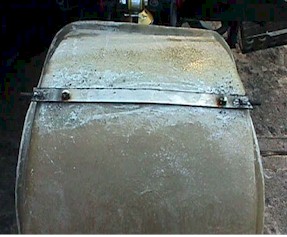
| SEAT Original setup (Scroll down to see the REDO) Most Diablo builders opt to mount the seats permanently with no adjustment due to high clearance. I am 5'11" and I wanted to be able to adjust the seat and so my wife could drive it too. I began to see what I could come up with. I tack welded everything until I was satisfied It would work and my wife agreed. I first started by finding the "center" of gravity of the seats and determined where they could pivot the least but with the most adjustment. I then marked that on each side of the seat. | |
|
|
|
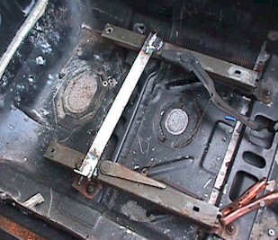
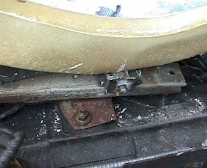
| I cut a 1/8th piece of steel about 15" long and 3in wide I cut slots on both ends and welded a bolt in each slot. | I then made L brackets and tack welded them in to position to accept the bolts. |
|
|
|
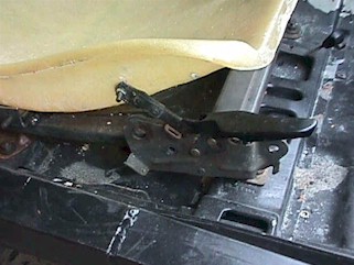
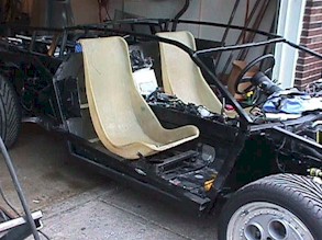
| This is the 1st stage. The bolts act as a pivot and do not interfere with the function of the seat rails from the original Fiero. | After the seat was in place I checked for clearance and the height was not too bad. My wife and I could both sit without hitting our heads. |
|
|
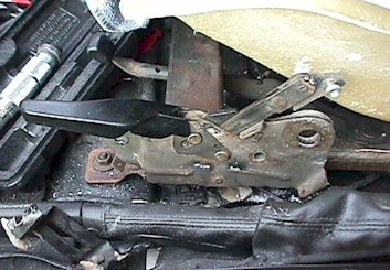
| I then had to devise a way for it to adjust and stay in a locked position. | I turned to the original Fiero seats and removed the seat adjustment bracket and assembly. I cut off the upper long piece and came up with this. |
|
|
| You can see that the adjustment will allow for the seat to be tiled forward or back and locking it into position. | (Passenger Side) View |
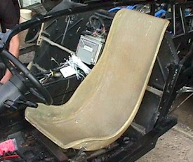
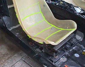
| I plan to reinforce the seats with 1/2 in square tubing (see yellow below)and a steel plate where the pivot bolts to the seat. I think this will work out fine. | |
 |
 |
 |
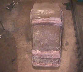 |
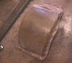
| I installed 1/4" round steel on the back side of each seat and then glassed it in. The seats are now very rigid and stiff. I was worried about flex but it does not seem to be a problem. | |
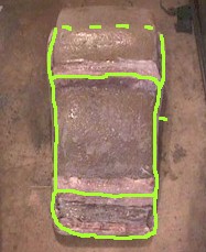 |
The yellow shows where the steel was glassed in. It was done from the back so it is not seen. It should be a great improvement in feel and rigidity. |
|
Seat Redo #2 |
|
 |
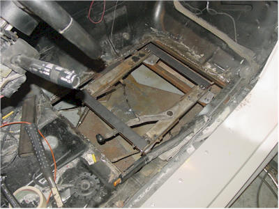 |
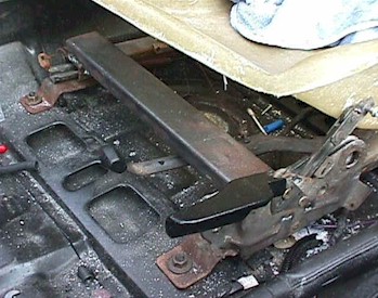
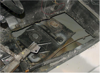
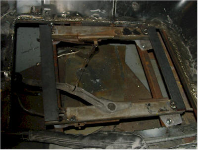
| Step one, using my plasma cutter I carefully cut out the floor pan. One of the things that you must keep in mind is that this small area is what connects the front and the rear sub frame. The Seat mounting is also used to reinforce this area. Removing the floor pan will require you to reinforce this area again. I cut just to the edge of the gas tank cross member and followed it just near the end of the front sub frame. I cut along the out side and then towards the back sub frame. | I reinforced the opening with 1 X 1 steel and made sure I welded the sub frame together and connected it to the outside frame.. I welded two new seat rail supports on the underside of the new steel. |
 |
 |
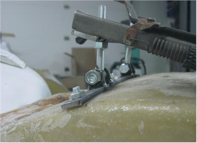
| Another close up of the new steel. I was able to mount the seat rails closer together to fit the seat better and connected them with 3/16" flat steel. | I wanted to be able to raise and lower or "tip" the seat if in needed to so I created a pivot point in the rear and made it adjustable from the front. |
 |
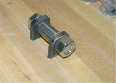 |
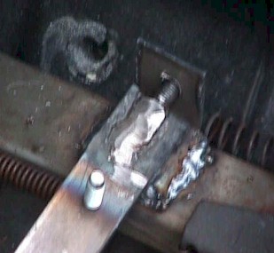
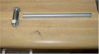
| The pivot is made from 7/16" rod and spacer. | I cut 1/4" brackets to hold the pivot bolt |
 |
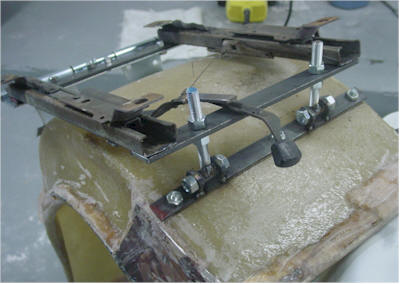 |
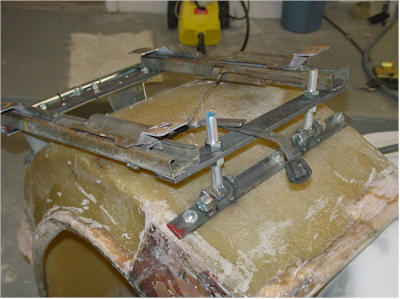
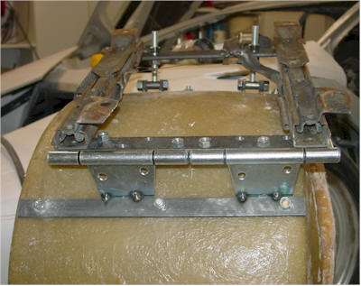
| The seat is upside down and is tack welded to show you how the mechanism works | I welded the Threaded rods to the spacers and then the brackets to the 1/4" flat rod that is bolted to the seat. |
 |
 |
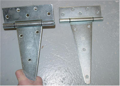
| I thought about the rear pivot point for a long time. I wanted a very sturdy and quite mounting point. I found some strap hinges that had plastic bushings making the very quite and smooth. | I bolted on end to the flat bar on the rails and the welded the other side to the flat bar on the set. (Both flat bar steel is 1/4" for rigidly and support). |
 |
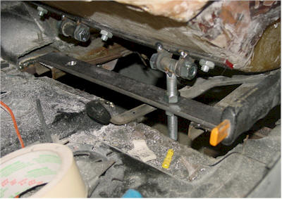 |
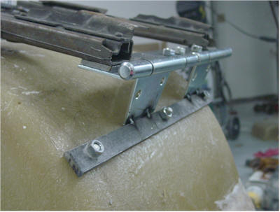
| You can see here how the rear pivot works and how sturdy and neat it looks. It is slightly offset by design however it does not affect the quality of the job. I offset it because I did not want the spring to touch the side so I moved in that side. | Here is an example of the seat installed. You may have to re-welded the lever. You can see in the picture that there is not much room to slide it over, however if you look in some of the previous shots I actually cut it off and added some steel to move it slightly over so that it would not hit the bolt when moving it. |