 |
|

| Home | Current Progress | Donor | Engine | Chassis | Exterior | Interior |
|
|
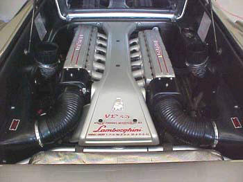
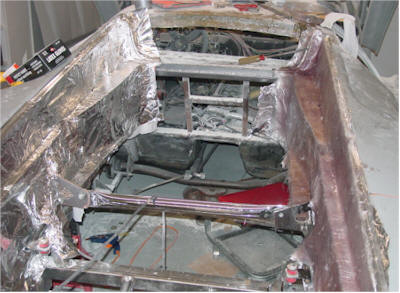
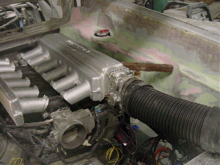
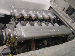
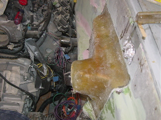
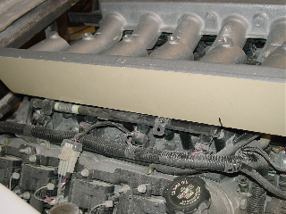
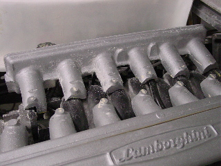
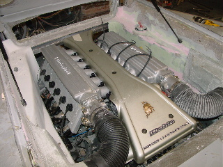
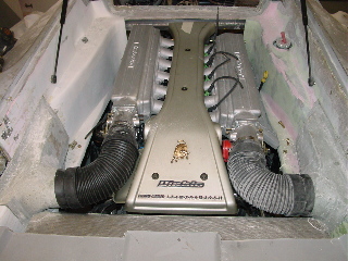
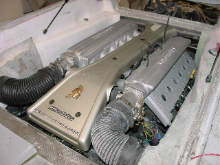
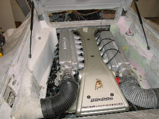
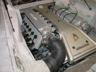
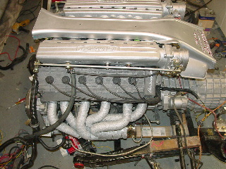
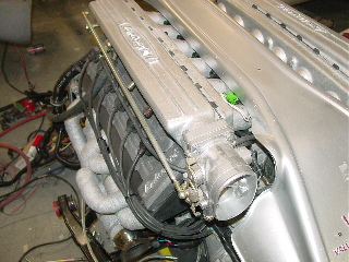
Engine Bay In order to create an authentic engine bay you need two things lots of pictures of the real thing and creativity. The first thing that must be done is to make sure the engine, and all the "plumbing" it done. This is to ensure that you fit your walls around your engine and not the other way around.
|
|
 |
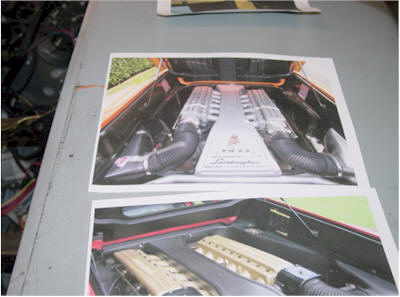 |
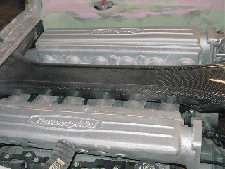
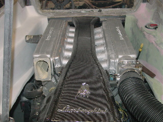
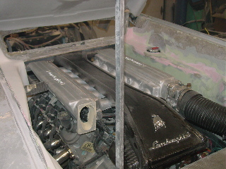
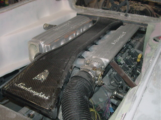
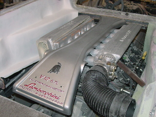
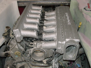
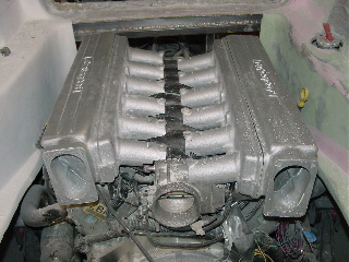
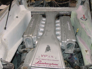
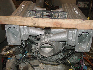
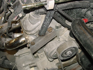
| This is a picture of what we are trying to replicate. | Here are some pictures taped to the rear fender for easy reference! |
 |
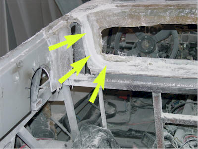 |
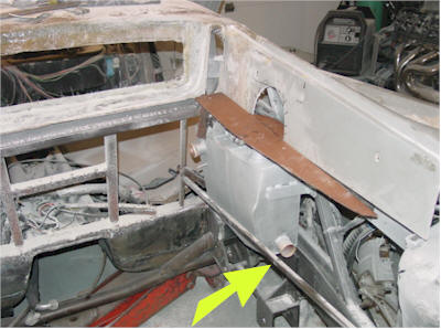
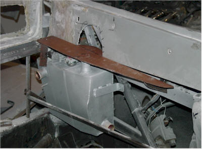
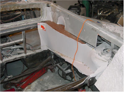
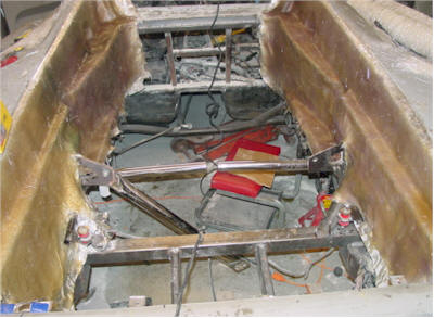
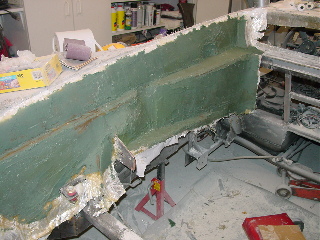
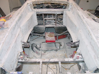
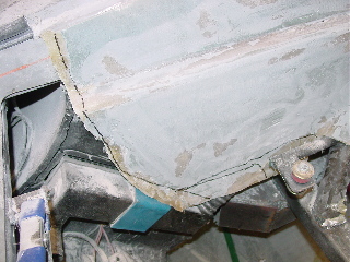
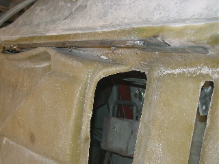
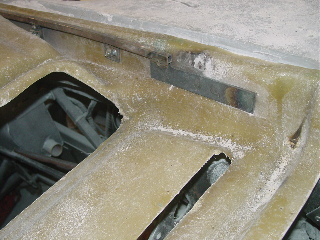
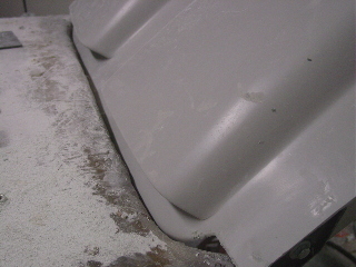
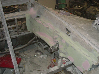
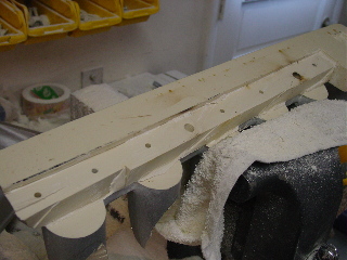
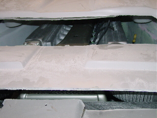
| The first step is to rough out the panels around the engine. The 1/4" square rod was tack welded while the engine was mounted and outlines how close we can come to the engine without getting too close and far enough away from the exhaust to remain safe. | The hole where we extended the roof was filled in and we added a "groove" to the window sill which will allow the panels to fit perfectly to the body. |
 |
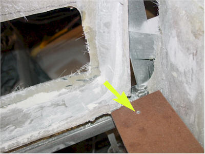 |
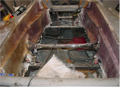
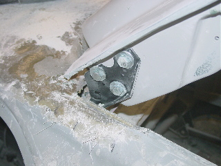
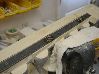
| The first "panel" rough-in is in place. It is simply made using a cardboard template traced on a piece of "hole-less" pegboard. | We riveted a piece of sheet metal that is bent and tack welded to the frame to correctly position the piece. |
 |
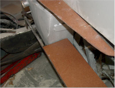 |
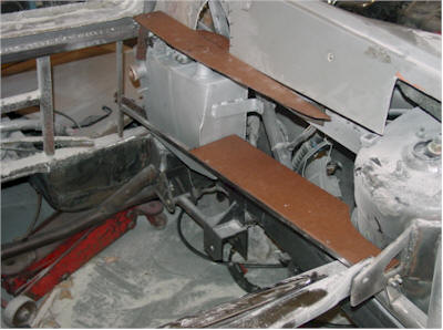
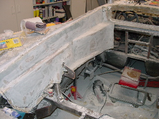
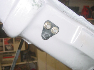
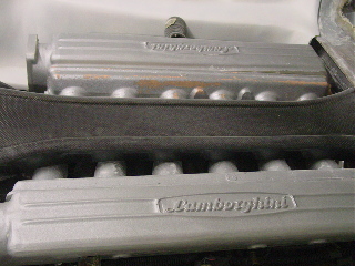
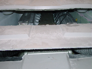
| The top and bottom pieces are in. Both are riveted to the metal. These will be removed later after the panels are done. | Close up of the two pieces. |
 |
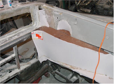 |
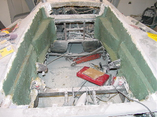
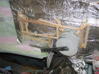
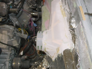
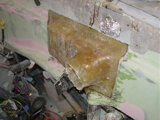
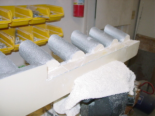
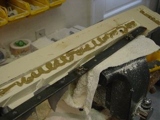
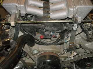
| The next step is to provide the contour of the side panels. This is accomplished buy using stretchy fabric The same that is used to make tee shirts. It is 100% cotton to prevent resin from eating though. All you do is use a hot glue gun to attach and stretch taunt. | Here the front part is formed along with the inset for the coolant fill. |
 |
 |
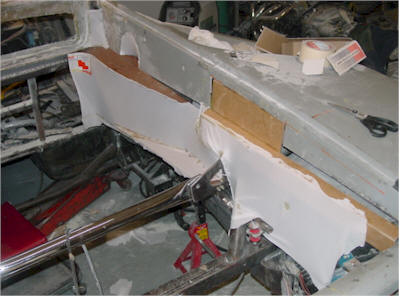
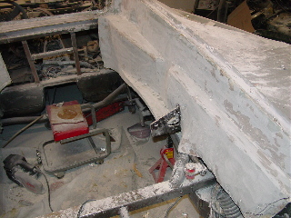
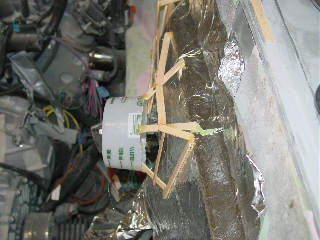
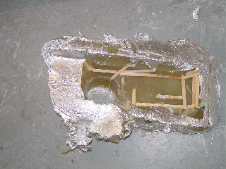
| The holes are filled in with cardboard and a cardboard side piece is created to cover the strut bolts and continue back to the air boxes. It is not important to make it "hole-less" only to form the contour of the side pieces. | Close up of the rear panel pieces. |
 |
 |
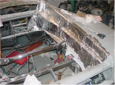
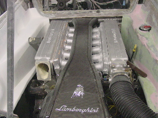
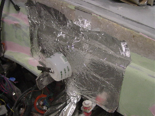
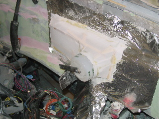
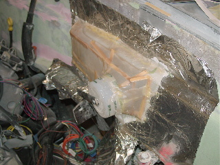
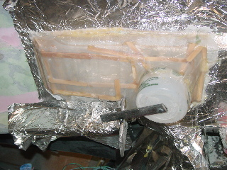
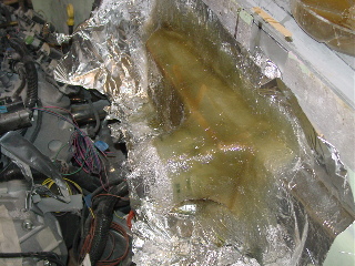
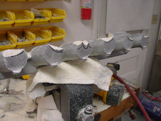
| The next step is to coat everything with spray contact adhesive and allow to dry for about 5 min and then coat everything with aluminum foil. You may have to spray more contact adhesive where the aluminum foil over laps. You do not want any surface that is not firmly attached to the "walls" | The next step is to begin to lay the fiberglass over the aluminum foil. The first layer needs to be thin and overlap each piece at least 1 inch. This to allow the glass to form to the curves. |
 |
 |
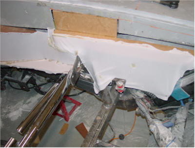
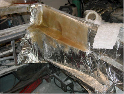
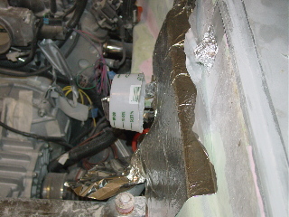
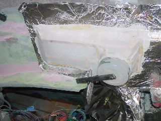
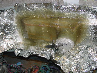
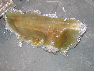
| We continued to the rear as one solid piece. | This is the first step of the first piece. |
 |
 |
| While the first side it tacking up, we started on the other side | We went back and while the first side had "kicked" but still soft we added a second and third cost of glass and then repeated that on the other side. |
 |
|
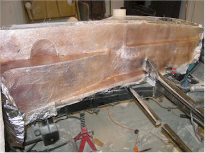
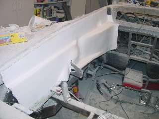
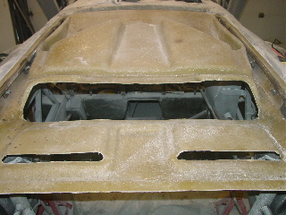
| Here is
a view of the finished sides. Stay tuned as we progress to the
next steps. At this stage it is still not complete, but you can
see it taking shape. The whole process to this point is a two day
job. So you know the reason the aluminum foil is used it to create
a thin barrier between the body and the panels. When the sides are
done you will be able to remove them and then bolt them back in just
like in any production automobile. Update 11-10-2003 The fiberglass seemed a bit thin and we did not want the run the chance of air traveling through and cracking the fiberglass. I use this technique for the interior where that is not a problem so rather than 3 layers of glass we added 3 more layers so it made it very stiff and about 3/16" thick. The next part is the fun stuff.... stay tuned. |
|
 |
 |
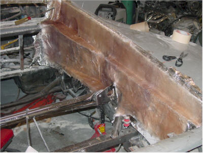
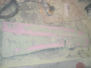
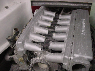
| The Next step is to coat the pieces with DuraGlass. This helps restore the flat contour of the pieces. As you know laying fiberglass in multiple layers creates many high & low spots that need leveling. | This is a view of the left side close-up |
 |
 |
| The left side is sanded down | and now the Right side |
 |
 |
| This was a messy job there is a thin dust coat over the entire garage. When I start the body work I will be hanging plastic sheets around the car. Just these two pieces made so much dust, I will be cleaning for a day. | I drew the line that will be cut to form a nice edge in the rear |
 |
 |
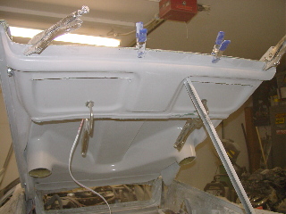
| I put a coat of primer on the left side piece to check the contour | This is the sanding mess of the right side. I am not going to prime this piece yet because I know it will require more sanding later when I fit it with the deck lid. |
 |
 |
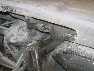
| In order to get proper placement of all the other pieces I had to rough-in the rear deck lid. I started first by position the steel supports that will run the length of the lid for support and provide the mounting locations for the hardware. | Another view. |
 |
 |
| The steel is in place and I ran the Electrical line for the brake light and then filled it all in with Duraglass. | I then positioned he top skin and then bonded the pieces together with Duraglass. |
 |
 |
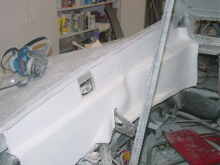
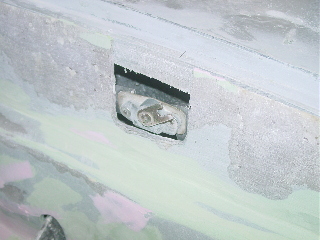
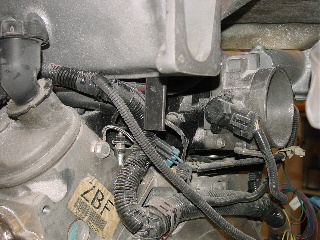
| In order to position the Ait boxes I need to locate the Latch. Theses are Original latches. | This is the latch pin (also original Lamborghini) located on the deck lid |
 |
 |
| This may be in the Deck lid section but since this is part of the engine bay area I decided to include it in this section. The Hinges are original Lamborghini | This allows me to correctly position the lid and it works great. |
 |
 |
| The panels are reinstalled to locate the latch holes | The Left side |
 |
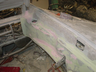 |
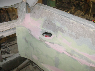
| This is the close up of the latch with the panel on. I will be opening it up like the original however at this point I did not want to cut out any more until I was sure it was correct. Filling a SMALL hole is better than filling a Big hole! | Another view of the right side. I have cut out the location of the Coolant tank fill. |
 |
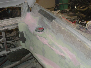 |
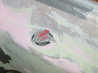
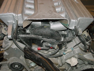
| Close up of the Coolant Fill area | I installed the Coolant tank and installed the Fill cap. |
 |
 |
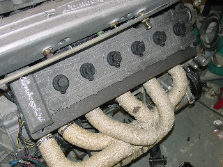
| Close up of this area | First trial fit. I duct tapped the Replica covers which are made from Aluminum "pregnanted" Plastic it looks so real! This is to allow for additional positioning of the pieces and to make sure everything was ok so far. |
 |
 |
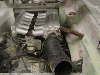
| I closed the Deck lid to make sure it cleared the top.... and DOUGH! the latches are installed with no cables yet to unlatch! That took about an hour to open up again... | In order to finish the air boxes for the side pieces I needed to get the placement of the Air tubes from the Throttle bodies. So I had to mount the "intake" The plastic is easily drilled and tapped and installing a flat bar steel allows for easy weld points. |
 |
 |
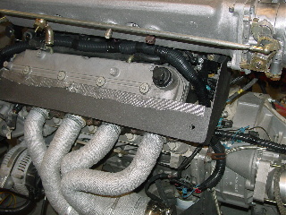
| The cover is tack welled in place by the steel on the intake and bolts to the engine. | The next step is to drill and tap holes to mount the Original Throttle bodies. |
 |
 |
| Cover is reinstalled with the Throttle body and original Air intake tube. | Another view |
 |
 |
| Well small problem.. TheLS1 sits a about 2 Inches too high because after installing the Throttle bodies I tested positioning with the Deck lid closed and the lid hit the tubes coming off the engine. I could angle them down but that would deviate from the originals "look" so I began to "Mark-Cut-Grind-Refit" about 2 hours to drop the whole assembly down 2 inches. | The extra work pays off and the cover is almost in the exact position as the original. |
 |
 |
| Here is the pieces just "sitting" on the engine. At this point I did not want to spend another 2 hours drilling and taping the steel until I was sure the pieces all fit. | Another view and all seems perfect! |
 |
|
|
Ok here is is ours is on
the LEFT the Original on the RIGHT |
|
 |
 |
|
Couple more shots! |
|
 |
 |
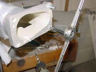
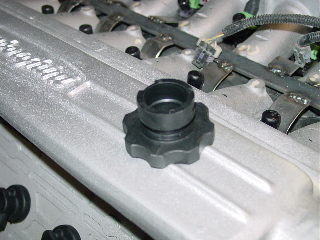
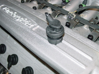
| Did you notice the engine cover switch.. We have like 3 and a 4th one is coming.. talk about anal huh! Well there is a method to all this madness and I have to get correct placements of the engine cover before I could continue with the sides and the air boxes. With is all secure I moved the air vent into the correct position. and stuck a plastic round cup to determine where it was going to go and drew a line where the cup met. | The next step was to cut around the cup and move the smaller end closer to where the air tube would be clamped on. The reason I used the smaller end was because I plan on making it all out of fiberglass and if the cup was "snug" on where it was supposed to be then any added fiberglass would make the opening to big for the air tube to fit over. |
 |
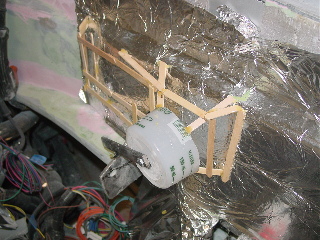 |
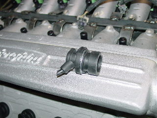
| Here is another view. The same technique was used to make the air boxes as the sides. 3M adhesive, aluminum foil..... | ...and this time popsicle sticks to make the framework. I also drilled out a piece of flat bar and tack welded it to hole the cup. |
 |
 |
| another view | and another |
 |
 |
| i then stretched the cloth out and glued it on to the framework | another view |
 |
 |
| and another view | I then put a coat of JUST resin over the cloth and let it sit up. Since this is a small part this allows the "structure" to have some rigidity while laying glass. |
 |
 |
| The resin is dry and we can begin adding the fiberglass | The first coat is completed |
 |
 |
| Then we add a second coat | Here is the piece after it has set and removed from the car. |
 |
 |
| The reverse side looks bad but you can now remove the foil and sticks. | I drew the lines where I wanted it cut out and then trimmed the piece to fit |
 |
 |
| another view | After completing the other side I glassed over the hole since it is not functional and I will be clamping the air pipe over it, I felt this gave it better support. If I were making it functional I would have made 4 or 6 coats of glass. Since this is for "looks" 2 was enough. |
 |
 |
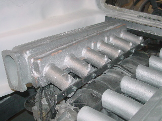
| The Next step was to take my new (Not the Prototype) intake pieces and get them mounted and fitted to the engine. The First step was to position them in the location they need to be. On a Lamborghini the intake is offset where the Passenger side it further back than the driver's side. If any one purchases this "kit" from www.lambostuff.com you may or may not need to do any special fitting. Because we have an SV deck lid it needs more room to clear the top. So I had to grind the intake runners to fit the LS1 intake. | This starts with a marker that you draw the contour of the runner pieces. |
|
|
 |
| another view of our marks | In order to make the Runner piece sit further down we had to cut the material where it sits almost parallel to the fuel rail. |
 |
 |
| First I cut the area where the fuel rail was | Then using an Air saw I carved out the area on the runners to allow them to sit flush. This may be a very time consuming process. You do not want to cut too much off so it took about 3 hours of marking, cutting, sanding, refitting, measuring and repeated. I did this until I was happy with the the level they were at and repeated the same on the other side. |
 |
 |
| This is the completed sides | Another view |
 |
 |
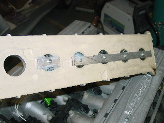
| The next step is to create a mounting platform so I could attach it to the engine. | Surface area is always a good thing to have. I first cut a piece of flat bar steel drilled holes tapped and screwed in the piece of metal. I recommend that you drill with a bit 3 times smaller than the bolt you are using. You may not need to thread the hold if you move slowly. DON'T force it or you can crack the plastic. You want to be able to screw the screw in with minimal force. |
 |
 |
| Once you have all he holes made using Urethane construction adhesive I coated the back and the screw holes and fasten the flat bar to it. You will also notice that there are two nuts welded on the flat bar to provice a strong mounting point for the side pieces. | This is a picture of the attached side pieces. |
 |
 |
| A quick check with the cover and all is good | I am taking advantage of having the engine out of the car to do the brackets. You can see this is the brackets I made to mount the front potion of the cover. |
 |
 |
| Hear is a picture of the rear brackets. Basically all I did was make a plate to bolt to the engine at all 4 corners of the cover. I then connected the steel from the cover to the Engine. Then to remove I can simply unbolt the plates (no part of the brackets) | Before I blindly began to weld I made sure it was all level one last time |
 |
 |
| Here is a close up of one of the plate I made to attach to the engine. | Another view of the other side |
 |
 |
| Pictures of the rear portion. I used the Throttle lever tube to ensure everything was square and aligned. | The fist connecting piece. You want to make quick passes as to prevent from burning the plastic or the adhesive you are using. If you have a HEAT block putty now would be a good time to use it. Otherwise you can do a quick weld and then get a piece of ice ready to cool the area around the plastic. |
 |
 |
| I removed the pieces with the new brackets | Next I needed to connect the pieces together. I simply drilled 1/4" holes and cut 2" pieces of 1/4" rod and used Epoxy to hold them together. |
 |
 |
| Another close up of the bracket | The next step was to use a flat bar and tack each of the protruding 1/4" rods to it to make a "base" for the soon to be relocated coil packs and fake fuel injection, |
 |
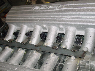 |
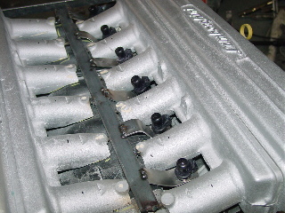
| Here the bar is in place and I have began making the brackets to hold the replica fuel injectors | Another view |
 |
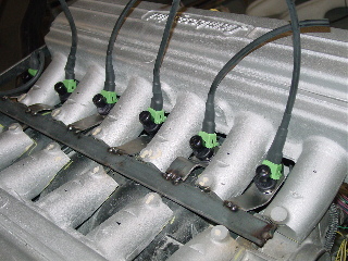 |
| Here is the view from the top with the Injectors in and the cover on. | Adding the finishing touches... I made real snap on plugs for the "Injectors" They are even the same "green" color as the originals. I slipped over a small vacuum line and used heat shrink tubing to make it even more authentic. |
 |
 |
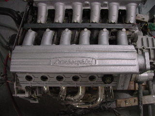
| Close up of the Injector brackets.. | Oddly enough the replica valve covers fit perfectly around the stock oil fill. This is great because we can disguise the cap to look like the rest of the replica spark plug wires! For now we are just testing functionality. |
 |
 |
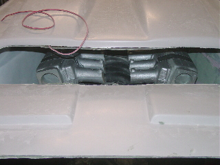
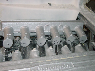
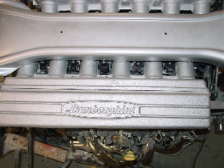
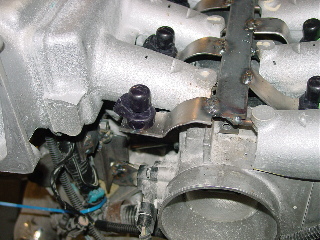
| It looks SOOO real | Here is a shot from the top down which is what most would see. In order to get it so flat we removed the coil packs where we will be installing them at the top under the engine cover. |
 |
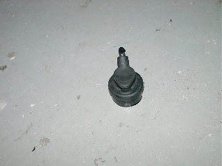 |
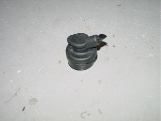
| Ok next "stop" Using an original spark plug boot from a Diablo I made a mold of it and then produce a "plug" AKA a prototype. | I recreated the mold from this part to all allow for the insertion of a "Fake" spark plug wire. These pictures are not showing the wires and were tested for fitment first. |
 |
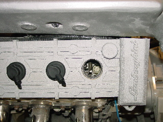 |
| The "plugs" fit perfectly into the "valve covers" Since on the LS1 the oil fill location just happens to be perfectly placed under one of the "plug holes" I widen it slightly and the cap fit perfect | Well if you have followed my progress so far you will know that I am very picky on how things looked so I thought I would make a "special" oil fill plug. |
 |
 |
| Removing the screw potion of a new cap I got at Autozone I made another plug with no bottom portion and then glued then together. | Here you can see the "Fake" plug top and the Oil fill cap bottom part. I will be making a mold of this to make the finished part |
 |
 |
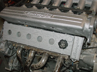
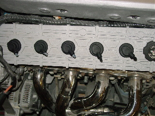
| Another view of the prototype | Here is a test fit of all 6 plug tops. No one would ever know the 6th plug could unscrew to fill the oil! The next step is to make the rubber and mold in the wires for a total OEM look. Stay posted! |
 |
 |
| I decided to go ahead and test fit all the pieces once again to make sure everything was fitting ok. I closed the deck lid to see what a curius onlooker would see as they pass by to peek. | there is no doubt that there is no way anyone could tell. We were able to capture almost every detail of the original V12 beast. |
 |
 |
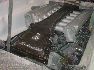
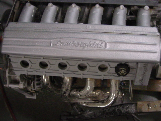
| I still have much to do but I could not stand no knowing how it would all look together. Upon installing the last air vent and putting on the rear lid, I was almost astonished of how real it looked. | I still have to fasten the fake Injector wires and we installed the original engine cover top for the full effect of this finished piece. (Thanks to Tony) |
 |
 |
| The right (Passenger side) vavle cover is laying on top of the coil packs. You can see that it can stay there and still have the effect but we are going to move them soon to bring it closer to the real valve covers | Another view |
 |
 |
| Another view | Yet another view. |
 |
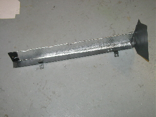 |
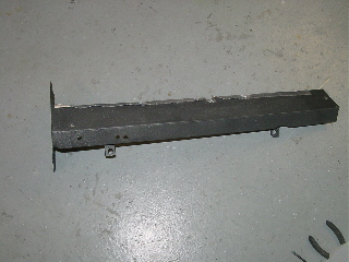
| Engine is out again and it was time to start doing the finishing touches on the engine cover. We wanted to increase the surface area of the "Valve covers" and wanted to create a good heat shield. Buy increasing the width of the covers it created both a lip for heat to go around and covers up the real spark plug wires and presented the possibility to disguise the engine with two more exhaust pipes. | This is the plate that the covers will bolt to. To increase it effectiveness for being a heat shield we also added a heat mat on the underside. |
 |
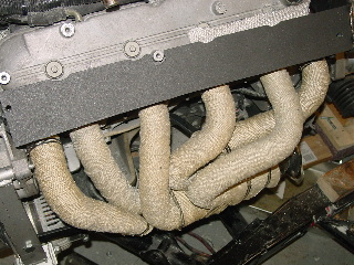 |
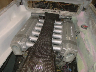
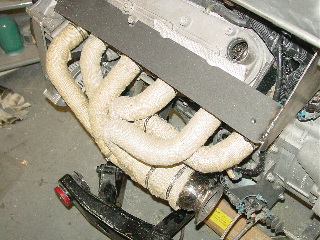
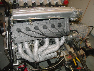
| You can see here that not only are the beautiful headers are now covered with header wrap there are now 2 extra on both sides for the V12 look. We added the wrap for several reasons but the main one was heat. Heat on any scale has an adverse effect on performance and safety. Lamborghini does something similar to their headers by using thin aluminum over the headers. This wrap claims it will reduce engine bay temperatures up to 70% it was a trade off for nice shiny headers but we know its there and when looking down from the top while it is installed you barely see them anyways. | Here is another view of the headers the other side now and cover in place. The two pipes that were added are actually removable and are not welded to the real pipes. The header wrap also disguises these two additions very well. |
 |
 |
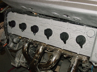
| The cover is in place alson with the "spark plug caps" We used the rubber type so even reaching down to fee them you can not tell they are not real. | When you install header wrap you must wet it to pull it tight and to make it pliable to wrap around the exhaust. when it dries it shrinks and tightens around the pipes. It is then recommended that you use special header wrap paint to seal it and to prevent stains from road grim or oil. We choose an aluminum color fo no reason except it matches better with the aluminum engine and makes them stand out a little better. |
 |
 |
| You can see how we attached the spark plug caps. Because they are rubber we wanted not only to epoxy it but added a thin pieces of aluminum with sheet metal screws. | Here are the finial touches to make the engine look like a real V12 engine. To mimic the spark plug wires we used silicone vacuum line that was made to fit inside the sprk plug caps perfectly. They are glued into place and routed to the front of the engine to a future "distributor cap from a real Lamborghini. |
 |
 |
| Every detail is painstakingly added including the original "vacuum lines" Throttle control and wires. We are even perfecting the Fuel injector plugs to use the Lamborghini pigtails that were ordered from Europe slated to be delivered in the next week. | |