|
Cradle |
|
 |
 |
|
When we sold the old engine (3800) we
swapped them out the cradle so that he would not have to do any
modifications to their own cradle for the engine to fit. So we
ended up with another dirty old cradle that had to be sandblasted
and ground and prepared for modification. |
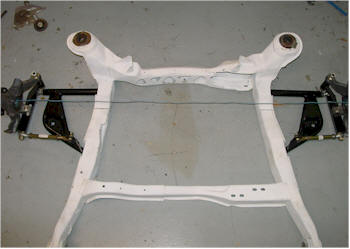
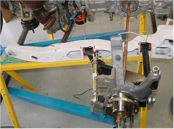
The first thing we did was
attempt to get the centerline of the axles on the cradle. For
that we installed the new rear bump steer kit from Held Motorsport
www.heldmotorsport.com
(See Chassis Suspension for more on that) Once installed we
ran a piece of string from the opening of the hub to each side and
marked the cradle. |
 |
 |
|
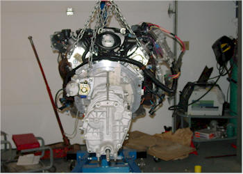
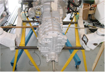
The next step was to
perfectly balance the engine and transaxle to where it was level and
straight while on the hoist. This part took a long time
however we finally got it perfect. We measured the axle flange
distance on both sides to the floor and they were equal on both
sides. We did the same thing from the engine mounts to ensure
it did not lean left or right. A level on top ensured the
engine was straight and level. The on nice thing about the
Fiero cradle is that is it flat on the bottom with allows for the
good alignment when mounting the engine. |
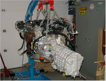
Next we put the cradle
under the engine and marked the approximate outline of where the
engine would be placed. The Fiero rear and front cross members had to
go. Many folks simply cut and modify the rear cross member
however we wanted it to be completely new. We were concerned
with weakening the metal if we simply cut it away to fit our engine. The LS1 engine sits very low as compared to a standard SBC
engine. |
 |
 |
|
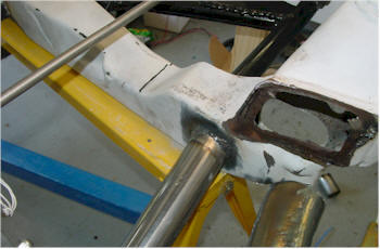
We then bolted the cradle back on to frame and then
cut the rear and front Fiero cross members out and then replaced it with
a temporary 1x1 piece of steel to keep it together. We made sure
that the temporary steel would not interfere with the engine
positioning using the marks we made on the cradle when it was out. |
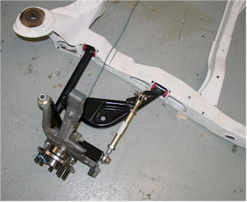
With the cradle back out and
positioned under the engine again, we were ready to begin alignment.
As with any car the axles should always be perpendicular to the
transmission or 90 degrees when the A-Arms are in the level
(Straight out) position. A few degrees off and wear increases
exponentially and eventually failure of the drivetrain. To
ensure we measured correctly we measured a stock Fiero's space
between axle centerline and the absolute bottom of the cradle.
Which was 6" exactly. or 5 1/4" from the bottom of the axle
and not the centerline. |
 |
 |
|
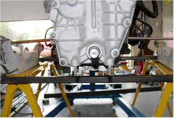
Then once we got the
correct height we located centerline on the transmission with a
symmetrical measurement. (Cradle bolt hole to the shift rod)
and then the Axle hubs. |
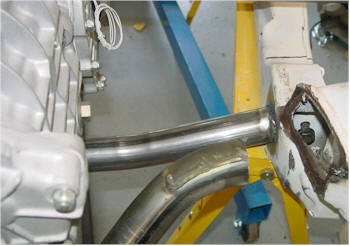
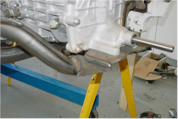
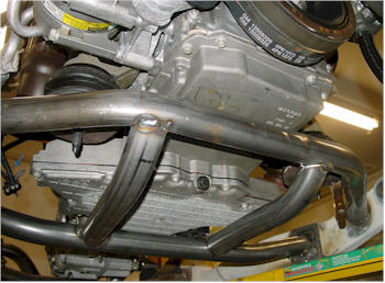
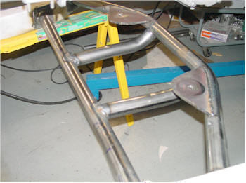
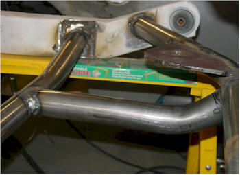
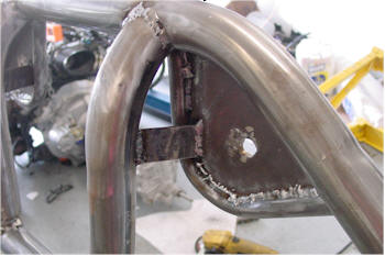
We then welded in a 1 3/4"
.095" round tube support and removed the temporary 1X1 steel bar. |
 |
 |
|
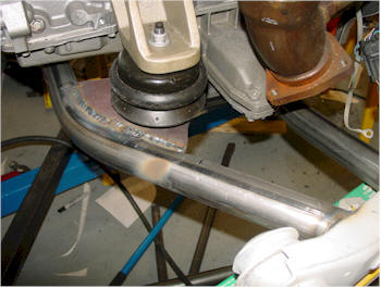
Another view of the new
support. You can see it was slightly bent as to clear the
bottom of the transmission. We simply used a tube bender with
a hydraulic jack. |
We then began to fabricate
a transmission bracket. We borrowed from Rick Page's design
and used a Total Performance
www.tperformance.com transmission cross member and added a
bracket that mounts to the bottom of the transmission. |
 |
 |
|
You can see that we first
made the bracket and then welded on the cross member. The ends
were added once we made sure the position was and alignment was
perfect. |
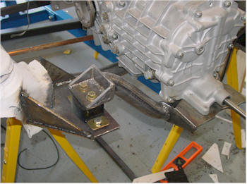
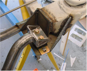
Using two standard GM
Transmission mounts we fabricated brackets from 1/4 steel and bolted
it to the cradle. |
 |
 |
|
Close up of the brackets |
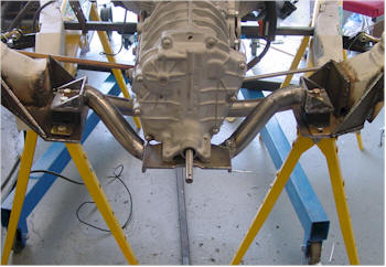
New Cross member in place
and transmission mounted. |
 |
 |
|
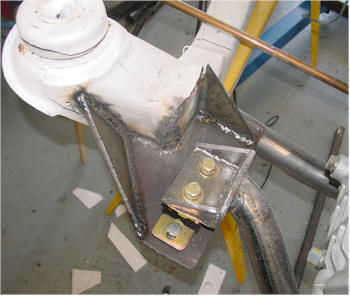
Left hand brackets with
extra support from 1/4 plate steel |
The next step is to
maintain the alignment while we fabricated the front area. We
measured from the engine mount to the cradle top on each side and
and divided that by two to get the absolute centering of the engine
in the front. Then we cut a wooden dowel with that measurement
(8-5/8") on each side. |
 |
 |
|
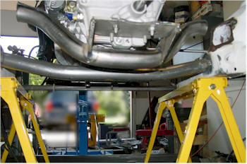
Doing what we did in the
rear we added new supports to the front and then removed the
temporary 1x1 bar. It was essential to keep the engine in
position while the new bars were added to ensure clearance. |
We then added the motor
mounts to the new cross member using 1/4 steel. |
 |
 |
|
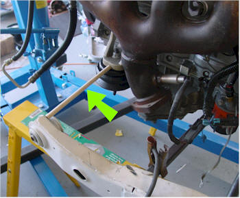
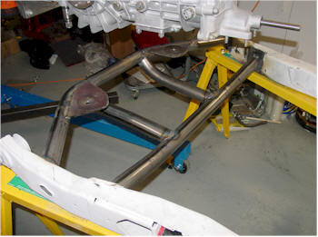
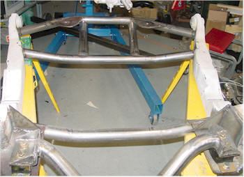
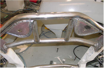
This is the almost
completed cradle. We are currently consulting on to whether
this will be enough support since the LS1 is mounted much lower than
most SBC engines. |
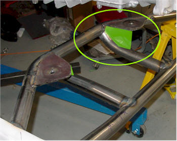
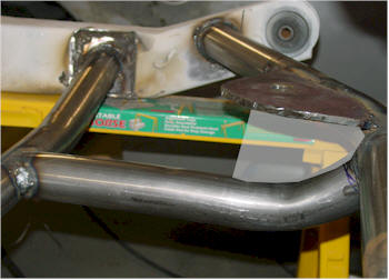
We will be adding some 1/4"
steel supports to the engine mounts (indicated by the Yellow areas) |
 |
 |
|
Cradle View |
Another Cradle View |
 |
 |
|
Close ups |
Close ups |
 |
 |
|
Close ups |
The transparent white area is where we
will be adding more steel |
 |
 |
|
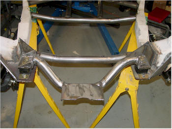
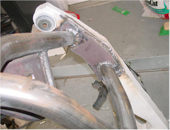
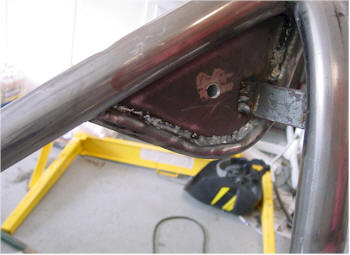
After some suggestions, we decided to
beef up the area around the front cross members and welded 1/4"
steel to the cradle and around the tubes. The stress by the engine
will be transferred to these points on the cradle and since it is
pretty thin and stamped we figured this would be a wise investment. We also added round tube around the
Engine mounting plates. Although it will probably not provide
much extra support it does provide for a finished look. |
 |
 |
|
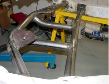
We then added the engine mounting
plate brace. |
Another view |
| |
|
| |
|
| |
|
| |
|
| |
|
| |
|
| |
|