 |
 |
|
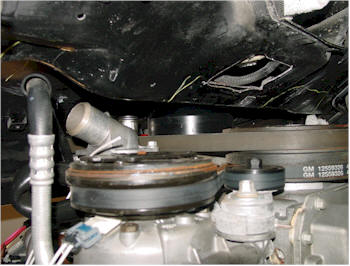
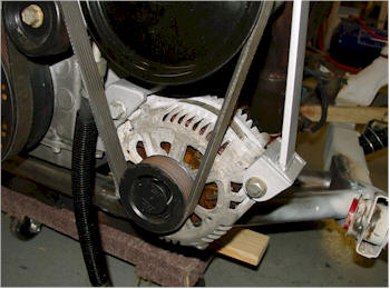
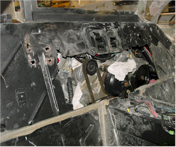
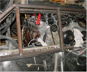
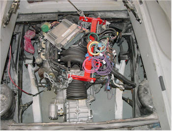
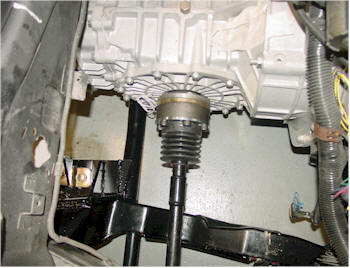
This is the shot from the bottom - up,
it is hard to see, but the only thing coming in contact with the
firewall is the water pump pulley everything else seems to have room
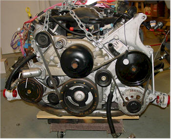
with the exception of the alternator. The alternator sits at
the uppermost part of the driver's side of the engine. The
firewall will have to be cut out there to clear the pulley. |
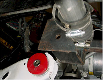
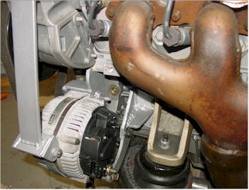
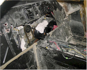
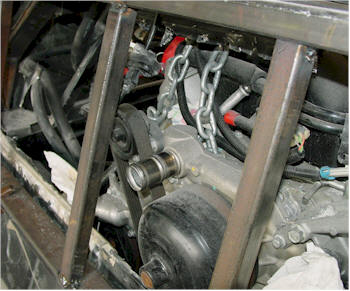
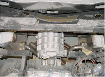
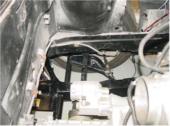
Another shot of how close it is
without modification. |
 |
 |
|
Rather than cutting the firewall I
personally did not like the alternator sticking up so high on the
engine, since I first saw it. In a Corvette there is no room to mount
it anywhere else. I began doing some research on if a company
made a re-mount kit for an LS1. I came up short everywhere I
looked, and then and I came across Vortech
superchargers. Their kit has a relocate system with the
Supercharger kits. After finally finding some installation
pictures, I found that it just moves it from the Right side to the
left side and only moves the problem and does not fix it. The
AC compressor sits on the passenger side on the lower part of the
engine and on the other side under the Power Steering pump there was
a wide opening, I thought it may be worth the time to see if
the Alternator could be moved there. . |
 |
 |
|
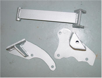
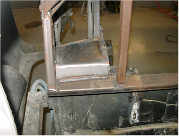
After about 8 hours of cutting paper
templates and trial and error I cut and made three brackets out of
1/4" steel. Alignment on an accessory is very critical I used
a level and calipers to ensure alignment before welding the brackets
together. What I found was nice was that the front of the block plus
1/4" steel made the alternator flush and aligned with the rest of
the accessories on that belt. There was about a 1/16" gap
(more needed) in the spacing and that was filled with a simple
washer. With the first mounting hold made I was then able to
construct the rest of the brackets. Probably one bracket too
much and we probably did not need to use 1/4" however I was not
about to take any chances. I coated them with aluminum paint
to match the rest of the brackets on the engine and installed them |
 |
 |
|
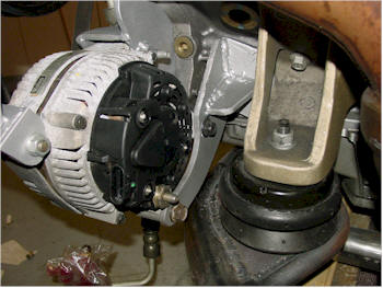
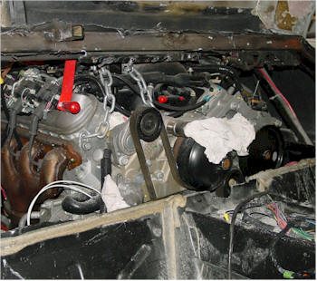
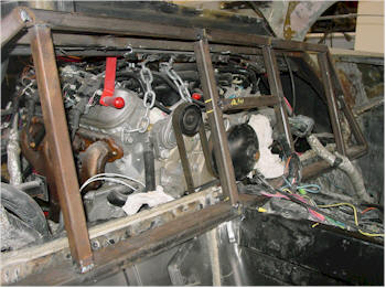
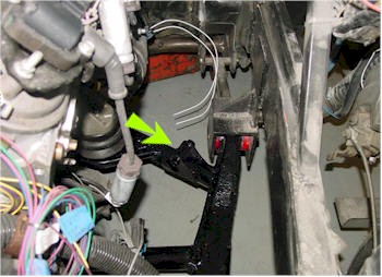
You can see here the old and new
alternator location. I will also have to re-locate the power
steering pump reservoir. This is not a big deal since it is
not pressurized I only need to make sure it is above the pump for
gravity to work. |
| |
|
 |
 |
|
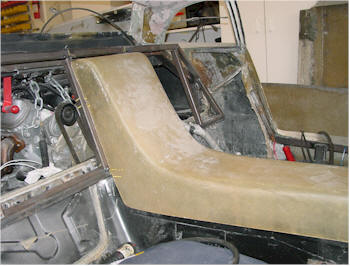
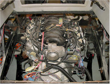
This is the first test fit of the
engine fully bolted in. |
It really looks bad to try and cover
up so we decided to completely gut the back firewall. |
 |
 |
|
The opened it up providing all the
clearance we needed. |
We started to fabricating the New
firewall support. and framed it so the engine would have plenty of
room. |
 |
 |
|
On of the first things we noticed was
how much room we had for the water tube that points in the wrong
direction...... We are working out a solution for this but we
did not let it stop us so we moved on. |
Everyday we work on this we get closer
to trying to make it look more and more original. We mounted the
Seatbelt crossmember. |
 |
 |
|
Test fitted the center console which
will be trimmed down from the top for an original look. |
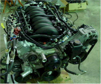
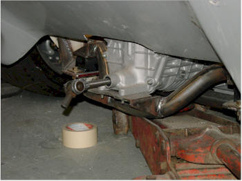
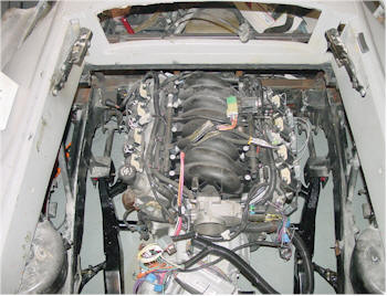
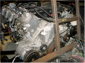
Here is the engine from the top, and
mounted. |
 |
 |
|
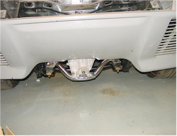
we had to trim the rear bumper support
to clear the transaxle housing. |
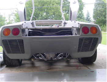
Plenty of ground clearance and
it will be almost covered by the bumper. |
 |
 |
|
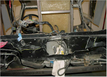
Rear view |
We took the engine out and focused on
the engine bay. It looked like a mess and since we cut out so
much it did not lend itself to any additional structural support. |
 |
 |
|
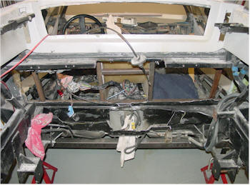
Another view of the mess |
Ahhh it looks much better all
the old supports were cut out and removed. |
 |
 |
|
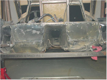
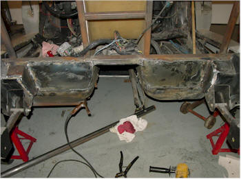
We capped the old cross-member with
1/4" plate steel |
We did this on both sides |
 |
 |
|
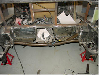
We then beefed up the bottom area
support with 1/4" plate |
The extra steel provided a strong
support area for the 2" .95 steel tube. We bend it to contour
the gas tank. |
 |
 |
|
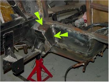
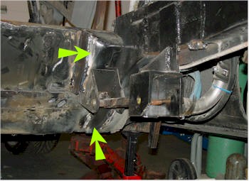
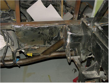
Note the extra side support that ties
in the original cross-member location. |
We cleaned up some of the other holes
with 1/8" steel. |
 |
 |
|
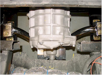
While we worked on the support we sent
out the cradle to be powder coated and the transmission mount chrome
plated. |
The engine installed on the freshly
coated cradle. |
 |
 |
|
We added an additional support bracket
before we had it coated. This will tie into a future support
to help minimize the V8's twist and torque. |
Shot of the rear with the Chrome
transmission support. The picture does not due this justice.
It is very sharp. |
 |
 |
|
We measured for the axles and had a
local Clutch and Joint (Dayton Clutch and Joint) mate a new Porsche
and Fiero axles into one. ours measured 26" however we also
have a +1 inch wide track rear end. We measured within 1/8"
tolerance. |
Another view of the axles |
 |
 |
|
Ok we removed the water pump and are
having a new inlet machined in it. More on that later. |
View from the top . |
| |
|
| |
|
| |
|
| |
|
| |
|
| |
|
| |
|
| |
|
| |
|
| |
|
| |
|
| |
|
| |
|
| |
|
| |
|
| |
|